Time Relay Schematic How Do You Wire Rockford Rfy004 Time De
Delay relay wiring Wiring diagram for 11 pin relays Time delay relay basics: relay circuit and applications
on delay timer wiring diagram | 8 pin timer relay wiring diagram | Mian
Delay relay time electrical timer schematic rockford wire do Dc schematic schematics electrical ac protection relays control diagram circuit example wiring relaying switch protective reading Relais electrique symbole – les symboles electriques – kuchi
Time relay diagram multirange schematic fig modelist konstruktor
Time delay relay circuit using 555 timer ic share project, 43% offDelay timer normally relay nctc timing control contacts Relay wiring diagram and function explainedTime delay relay circuit.
Time delay relayDelay timing relays Delay relay circuit time diagram circuits ii power timer schematic electronic iis gr next full here supply ic parts diyMultirange time relay.

Time delay relay
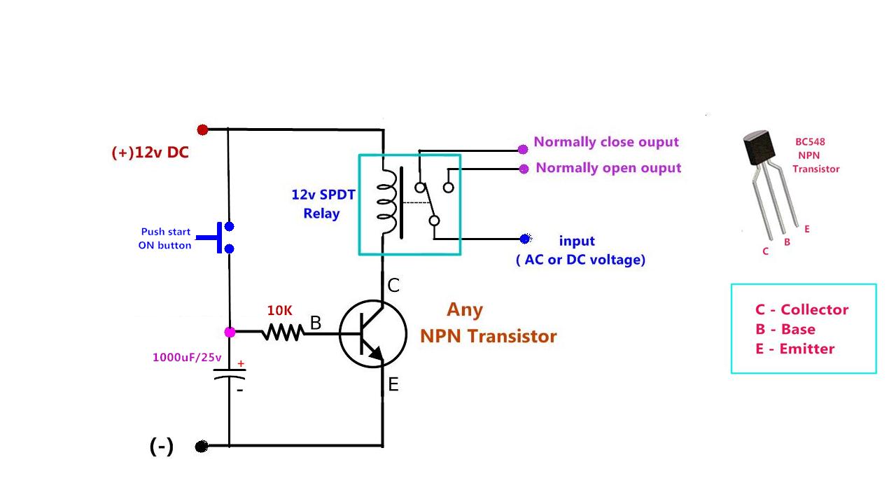
Time delay relay iiRelay off time delay timer by using npn transistor and capacitor Relay circuit delay time schematic diagrams circuitdiagram diagram switch sensor level frequently readers hello so add do8 pin timer relay wiring diagram.
Timer circuit diagramRelay diagram wiring delay timer off layout state relays solid base socket time connection control pins motor dayton pump 120v Simple delay timer circuits explained homemade circuit, 54% offOn delay timer wiring diagram.

Dayton time delay relay wiring diagram download
Study of electromagnetic contactor, thermal overload relay, timer (offTime delay relays explained Reverse overload relay circuit forward diagram motor wiring contactor power starter direct control dol thermal electrical switch magnetic connected onlineTime delay relay circuit using 555 timer ic share project, 43% off.
Relay delay wiring diagram time dayton motor timer wire symbol circuit schematic gear a652 symbols size connection full pull needDelay timer circuits explained wiring requested transistors Esp8266 relay schematic12v time delay relay circuit diagram.

Time delay relay circuit
Delay relay timer off time using npn power circuit transistor diagram capacitor dc gen driveHow do you wire rockford rfy004 time delay relay 12v time delay relay circuit diagramIn many electronic circuit applications a delay of a few seconds or.
Time relay – learnchannel-tv.comHow to build time delay relay circuit Relay delay time circuit working constructionAh delay timer and relay electrical circuit diagram.

Relay circuit understand principle
Time delay relay using 555 timer, proteus simulation and pcb designTime delay relay Electrical standards: overload relay working principle and features ofRelay time delay circuit symbols contacts basics applications four type.
Time-delay electromechanical relays : worksheet12v time delay relay circuit diagram Here’s a quick way to solve a info about how to build a timing circuitDelay time relay diagram timing relays electromechanical circuit electronics will when lamps.

Delay relay proteus simulation timer pcb
Reading and understanding ac and dc schematics in protection andRelay relays delay learnchannel overview .
.


